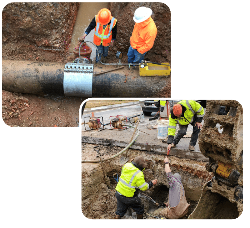
The Engineering Department offers many services ranging from plan review and approval of proposed water and sewer improvements for large scale development plans and subdivisions to pricing of tap fees for individual residential or commercial services. The department also offers upon request fire hydrant flow data and general mapping information when available.
Each member of the Engineering department is committed to aiding developers, companies, and individuals in their requests for establishing new public water and sewer facilities or services as well as providing pertinent information relating to existing facilities within the service boundaries of the Springdale Water Utilities.
- Standard Meter Service Easement Form (Acknowledgment for Companies)
- Standard Meter Service Easement Form (Acknowledgment for Individuals)
- Standard Water/Sewer Main Easement Form – Companies
- Standard Water/Sewer Main Easement Form – Individuals
- Water and Sewer Maintenance Bond Form
- Performance Bond
- Payment Bond Form
- Certificate and Affidavit Form
- Tap Relinquishment Form
- Request for Public Hydrant Flow Test Form
- Request for Private Hydrant Flow Test Form
- Request for Seasonal Meter Form
- Request for Potable Meter Form
- Petition For Annexation form
- Affidavit For Nonpotable Water Meter form
The Springdale Water Utilities is proud to make available limited online mapping of water and sewer facilities currently owned and operated by the utility. While the department strives to make available the latest most accurate depiction of existing facilities, inaccuracies may exist, and it is recommended that the information presented herein be utilized for preliminary planning purposes. It is highly recommended that you contact our offices to gain information on fire flow capacity, potable water capacity, sanitary sewer capacity, or for detailed investigations.
Click the button below to access the Water Springdale Utilities online mapping system.
Download specifications for the following:
Standard details:
- S-1 - Fire Hydrant Gate Valve
- S-2 - Fire Hydrant with Guard Posts
- S-3 - Reaction Backing
- S-4 - Vertical Tie-Down Blocking
- S-5 - Tapping Saddle and Valve
- S-6 - Water and Sewer Line Crossing
- S-7 - Manhole Frame & Cover
- S-8 - Manhole Frame & Cover
- S-9 - Watertight Manhole Frame and Cover
- S-10 - Watertight Manhole Frame and Cover
- S-11 - Manhole Bottom
- S-12 - Drop Manhole
- S-13 - Manhole and Main Abandonment
- S-14 - Manhole Height Increase
- S-15 - Manhole Height Decrease
- S-16 - Sewer Service Connections
- S-17 - Typical Pipe Trench
- S-18 - Pressure Pipe Trench
- S-19 - Pressure Sewer Pipe Trench
- S-20 - Concrete Encasement-Layout1
- S-21 - Pavement Removal and Replacement
- S-22 - Standard Meter Box
- S-23 - Meter Box Installation-Layout1
- S-24 - 1 Inch Meter Setting
- S-25 - Double Meter Setting
- S-26 - 2 Inch Meter Setting
- S-27 - 2 Inch Meter Lid Assembly
- S-28 - 2Residential Pressure Reducing Valve
- S-29 - Local Street Section Layout
- S-30 - Local Street Plan View
- S-31 - Encasement Details
- S-32 - Highway Boring
- S-33 - AirVacuum Release Valve & Vault
- S-34 - Swing Connection
- S-35 - Bypass Manhole & Quick Connect
- S-36 Fire System Connection
- S-37 Water & Sanitary Sewer Service Trench Repair
- S-38 Sanitary Sewer Main Trench Repair
- S-39 Water Main Trench Repair
- S-40 Sanitary Sewer Service Trench Repair
- S-41 Water Service Trench Repair
- S-42 - Fire Hydrant Placement
- S-43 - Manhole Bottom NON SHEAR COUPLING
- S-44 - Cut and Cap
- S-45 - Asphalt Street Repair Valve Raise
- S-46 - MH EXTENSION RESTRAINING COLLAR
- S-47 - CLEANOUT DETAIL
- S-48 - Food Truck Sewer Connection-Sewer
- S-49 - PVC Pressure Water Pipe Trench
Miscellaneous details:
- Hydrant Hot House-sheet 1 of 2
- Hydrant Hot House-sheet 2 of 2
- M-1 - Tracing Wire Connection Port
- M-2 - Frost Proof Yard Hydrant Assembly
- M-3 - Chain Link Fence
- M-4 - Chain Link Fence Hardware
- M-5 - Steel Frame Wood Privacy Fence
- M-6 - Barbed Wire Fence
- M-7 - Utility Marker
- M-8 - Meter Array #1
- M-9 - Meter Array #2
- PS-1 - Pump Station Profile View
- PS-2 - Pump Station Plan View
- PS-3 - Pump St. Site Plan
- PS-4 - Communication Tower
- PS-5 - SCADA Subpanel Layout
- PS-6-Onsite Split Face CMU Building Detail
- PS-7-Pump St. Electric Schematic-Pump Control
- PS-8-Pump St. Control Panel Layout
- PS-9-New Pump St.-Sump Pump Detail
- PS-10 - New Pump Station- ARV Installation
- PS-11-New Pump St-Details
- PS-12-New Pump St Pump Hanger

